
Tiny tiny components
We are currently experimenting with increasing the range on the scoreboard remotes. Right now we have about 55 yards, which is just about the limit of readability of the scoreboard. That’s great. But at that range the remotes aren’t working fantastic; sometimes they miss button presses.
One of the tests involves putting external antennas on the remote controls and the scoreboards to see if the increased sensitivity buys us some more distance. To do that, I had to modify one of our wireless modules so that it would use the u.Fl connector instead of the chip antenna. And that meant rotating a component 90 degrees.

The component had to be rotated 90 degrees. This small part is .01x.02 inches in size.
What you are looking at is the wireless module on a test remote, with a finger for scale. Just above the u.Fl connector is a tiny capacitor highlighted in a red box. I zoomed in with an inset to help a little more.
This component is sized 0201, which is industry speak for freaking tiny, and means .02x.01 inches. The tip of my soldering iron was larger than this component, and at one point I lost it in a small amount of solder. Fortunately I don’t have to deal with components this small very much.
Behind the scenes of a Kickstarter project
Running a Kickstarter project is challenging. Your life is tied to a number that you have very little control over, and that number defines you for the next month. Every contribution sends an email to an inbox, which chirps to give a bit of excitement.
Live in person stats
Since we’re all about sharing scores and encouraging everyone to get more engaged, we thought we’d share our numbers with you live.
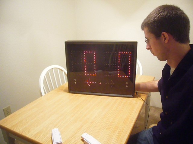
Here at Portable Scores we’ve been using one of our prototypes to track progress, putting our numbers in big red lights, having it beep every time we get a contribution. We put this display up at our hackerspace Sector67, which is where we did most of the development, and is a place where more people can see the scoreboard.
<tech speak> We’re using a raspberry pi and a python script to scrape the stats.json url of our kickstarter campaign. A bash script runs this python script every 20 seconds and displays the number of backers right justified, waits 10 seconds, and shows the % complete left justified (rounded up so we feel slightly better). The pi controls the scoreboard over USB using a serial string like so: echo “C1234000\n” > /dev/ttyACM0 </tech speak>

The Sector67 Web Camera. If the number is on the left, that’s % complete. If the number is on the right, that’s # of backers.
But these are the numbers that everyone sees. Here’s what’s going on behind the scenes:
Behind the scenes stats
This is what Kickstarter shows the project creator on the dashboard page.
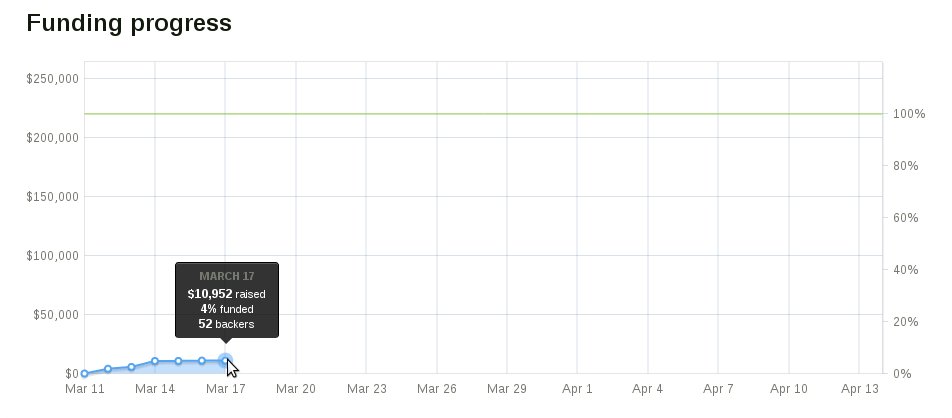
Our progress as of March 17.
This is a very simple graph showing our trajectory. Yep, we’ve raised $11k so far. So where are those pledges coming from?

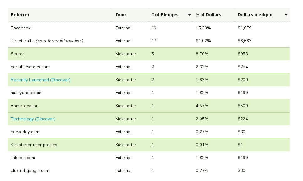
The graph above shows where our traffic comes from, but only shows referrers of backers. Kickstarter doesn’t show how many people visit the page or where they are coming from, nor do they offer conversion rates. We lack the data to improve our campaign, like total views, and referrers of non-backers. We do have a metric in video stats, which is a flashlight in this cave of mystery.

Are other people experiencing this challenge? It turns out yes, and Kicktraq is a site specifically for helping with those metrics.

It shows projections, more interesting graphs, and more data. Thank you, Kicktraq! It also shows how awesome my grandma is. $5000 from her alone! She’s the best!
Publicity
The key to a successful Kickstarter campaign is getting media attention. After tapping your social network, you still have a long way to go, and if you can’t get your target audience to see your campaign, it’s difficult to get traction. As you can see by our referrers, Facebook and our social network was our initial bump. So how does publicity help? A week before and on the day of, we contacted every media outlet we could, pitching different angles, announcing our launch, letting them know we were there and ready. Hackaday picked us up with an article on our molding process. This led to a substantial spike in traffic to our web site, as evidenced by our Google Analytics:
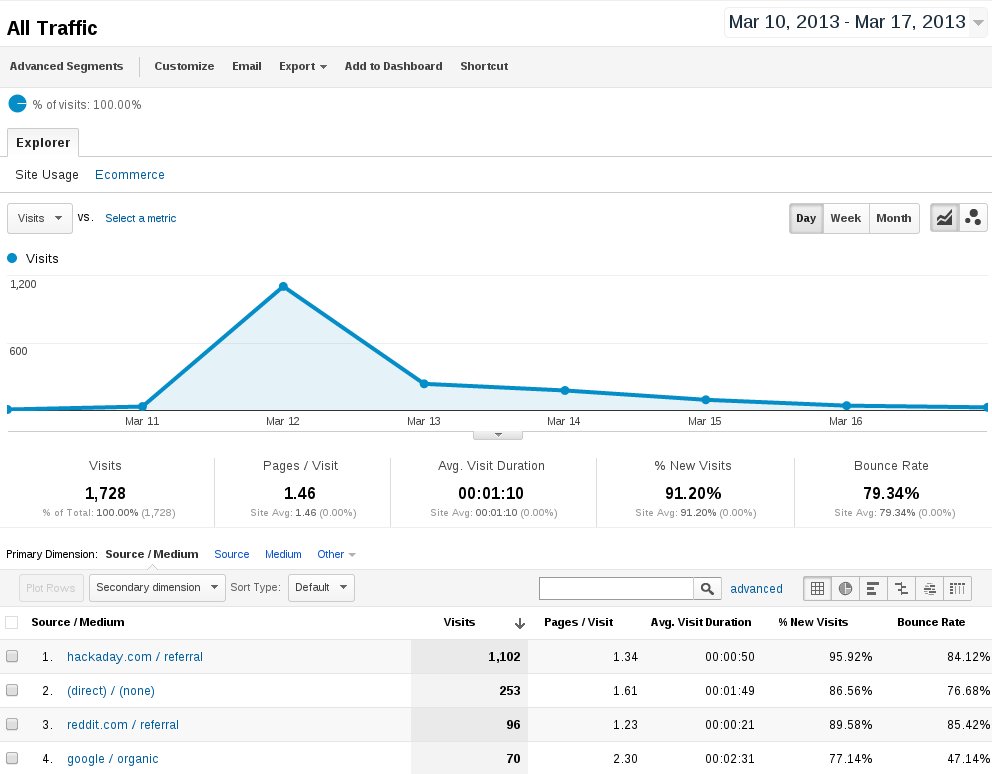
1100 visits in a day; not bad! How did that translate to conversions on Kickstarter? Looking up at the graph from Kickstarter, it means a single conversion. Admittedly, Hackaday wasn’t really our target audience for the scoreboard, but it is an example of how we can track media attention to conversions.
As our campaign continues, we’ll keep putting out articles and going after our target customers. We’ll use the data we can collect to refine our campaign and get traction.
If YOU are interested in a scoreboard, or supporting our project, check out our Kickstarter project now!
Request to product before noon the next day
We love our beta testers. They’ve given us great feedback, and have been real cheerleaders for our product. We recently heard from one of them, who said:
For the most part, our experience with the scoreboard was very good. We were able to quickly teach a number of officials how to use the scoreboard in a manner of minutes, and the parents and coaches appreciated being able to see the time remaining and score. Battery life was also very good.
The main negative was that for outdoor use, if the sun is out, it’s difficult to read the board. The numbers are washed out by the sun. On most days, we could only use the scoreboard until around noon.
If you’re able to solve the visibility issue, we’d happily purchase 40 or so units for our leagues. – John
That kind of feedback is very motivating, so we quickly got to sketching a solution. We wanted to do something that wouldn’t be bulky, would be easy to set up, wouldn’t break if impacted, and could also double as a screen protector. It would be nice if we didn’t need to modify the scoreboard design much, too. Oh yeah, and it had to block the sun.
We’ve tested the scoreboard in a variety of lighting conditions, including indoors and outdoors, in daylight and evening, and only rarely have this problem.
But we have Wisconsin sun, not California sun, and it’s very likely that they have it worse than we do.
Back to the solution! We started by whiteboarding it of course.

designing the part on the whiteboard
After spending a few minutes making a CAD drawing, I used a 3D printer to create a physical model. Magenta was already loaded in the printer, so magenta was what I got. It mostly fit, but there were a few tweaks to make. I changed it up a little, and the second run worked pretty well. Enough that I could make another and have a completely working prototype.

Closeup of the clips. The top one is the first draft, the bottom one has some tweaks to fit better.
So I printed the second one, and got to testing.
printing the part in magenta

the finished part is ready to test
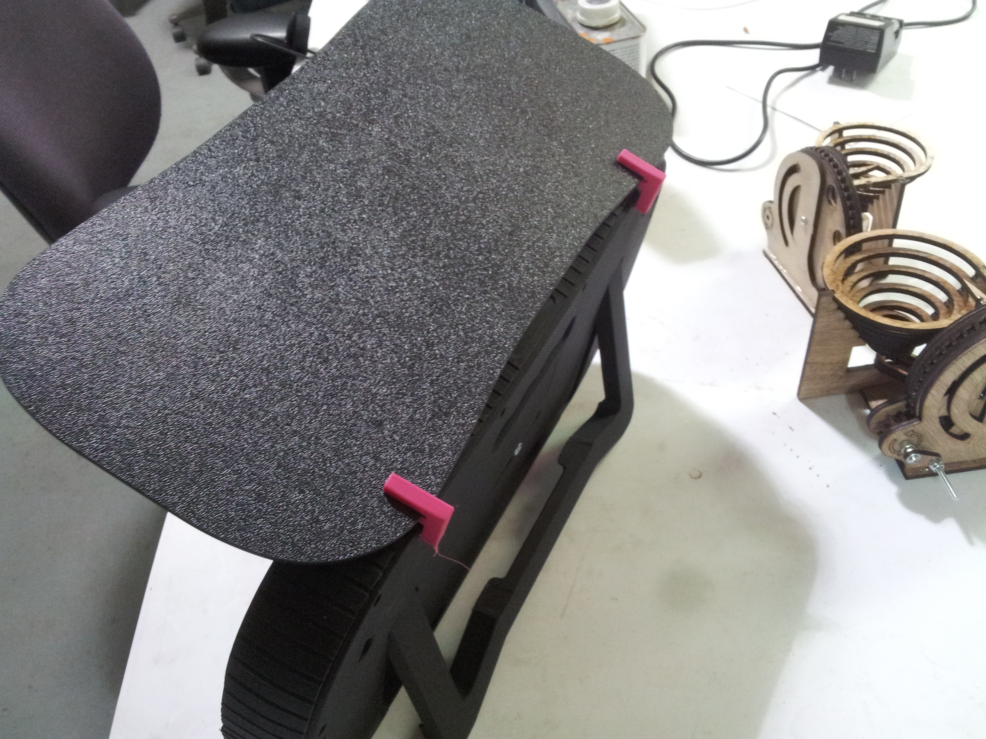
the assembled visor from the back.
Again, the Wisconsin sun was no help. The weather outside was overcast and snowing, and what light was making it through was reflecting off all the snow already on the ground and making the lighting conditions completely different from California.
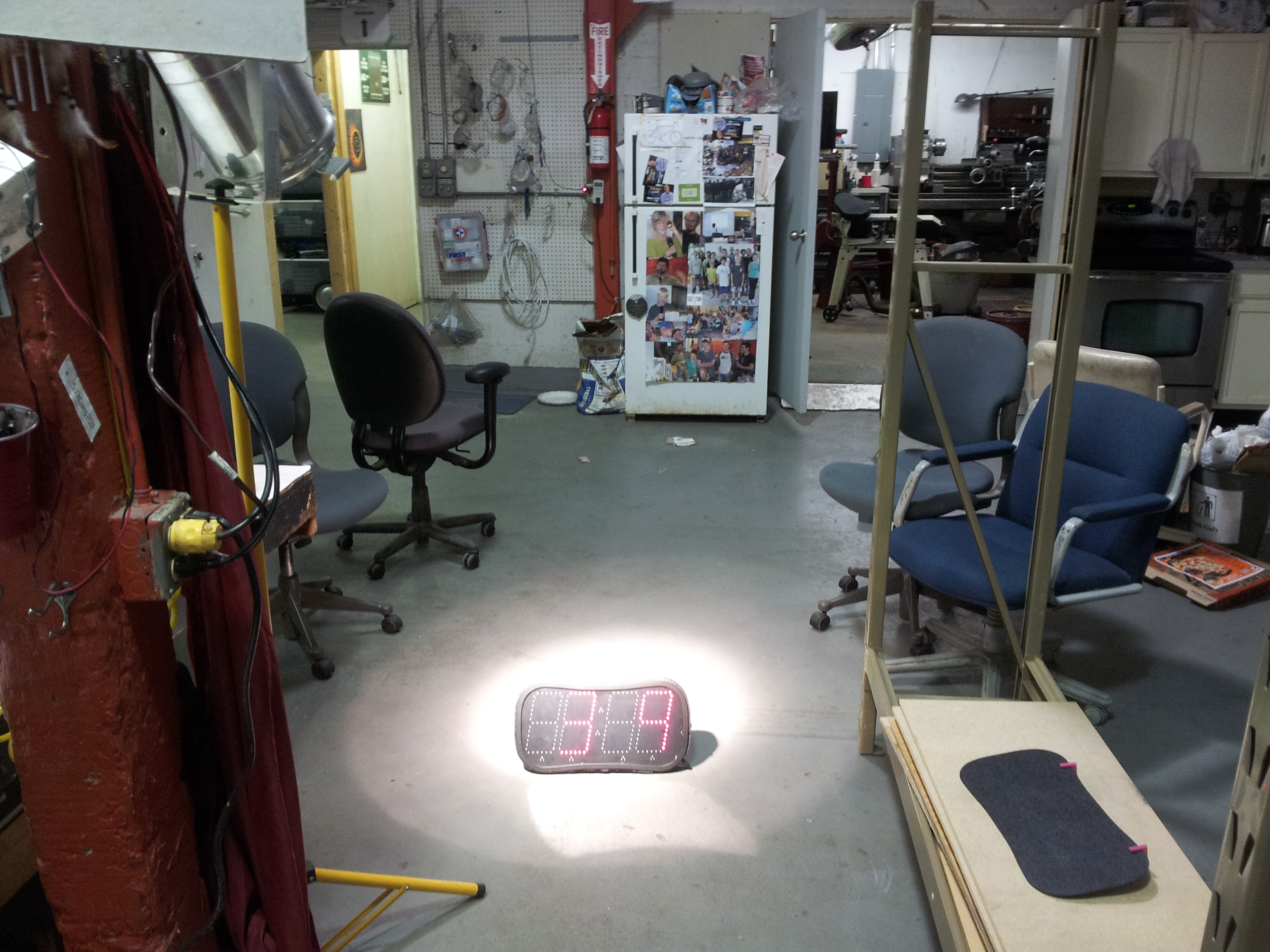
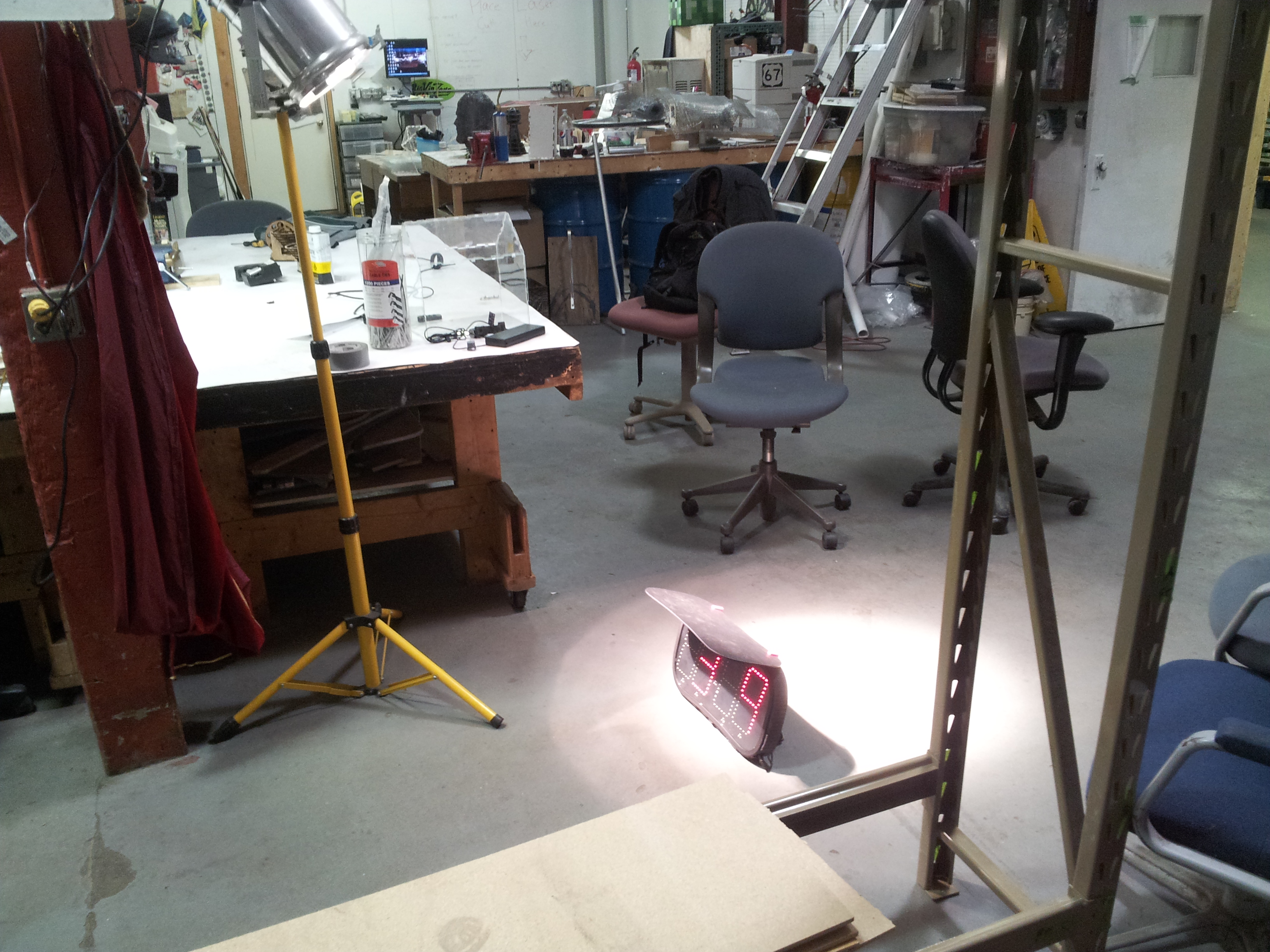
Fortunately, I could improvise. We have a spotlight at Sector67; a very bright one that gets painfully hot. And it was the perfect solution. I created a fake sun inside, and tested it out. First the image with no visor, and then with the visor.
Without the visor, it’s washed out as mentioned by our beta tester.

With the visor on, the sunlight is blocked.
A side view of the test setup.
This pretty simple solution solved every one of the requirements. I didn’t have to make any modifications to the scoreboard. The visor will fit snugly inside the bezel to keep the screen even safer in a backpack, the pieces snap off safely without damaging anything when impacted, and it even blocks out direct sunlight!

The scoreboard with visor over the screen, and two clips to attach to the scoreboard.
John, the Kickstarter page is at http://kck.st/16otSct. If you want I can send you these pieces so you can test it out yourself on your beta unit. I’ll do them in black for you.
Molding silicone
Around the outside of the DigiTally scoreboard is a rubber-like band. This band serves many purposes:
- Impact/scratch resistance
- Water resistance (seals a seam between the front and back
- Molded in buttons
- It looks AWESOME
During the development, this has so far been a simulated part; we have the design but never tested it out. We’ve been building a production-ready version of the scoreboard lately, to make sure all the parts fit together as designed and we wanted to have a rubber part. To print the other parts we used Redeye 3D printing service by Stratasys. They were kind enough to give us a 10% discount after we explained our starving-startup status, and shipped us a still-very-expensive set of parts. But the band was printed in ABS and wasn’t stretchy, so it wouldn’t fit correctly.
This was our opportunity to explore rubber molding. It would have cost a few thousand dollars to have the band 3D printed in rubber, and we couldn’t afford that, so we went to our local Smooth-On distributor, Techno-Industrial, and they gave us some great recommendations, as well as some sample parts to help determine which hardness of material to use.
We needed to make a mold using the part we had 3D printed as what is known as the positive. I started by making a frame for the mold. Silicone is expensive, so I wanted to use as little of it as possible, so I made the mold about 1/2″ out on each side.
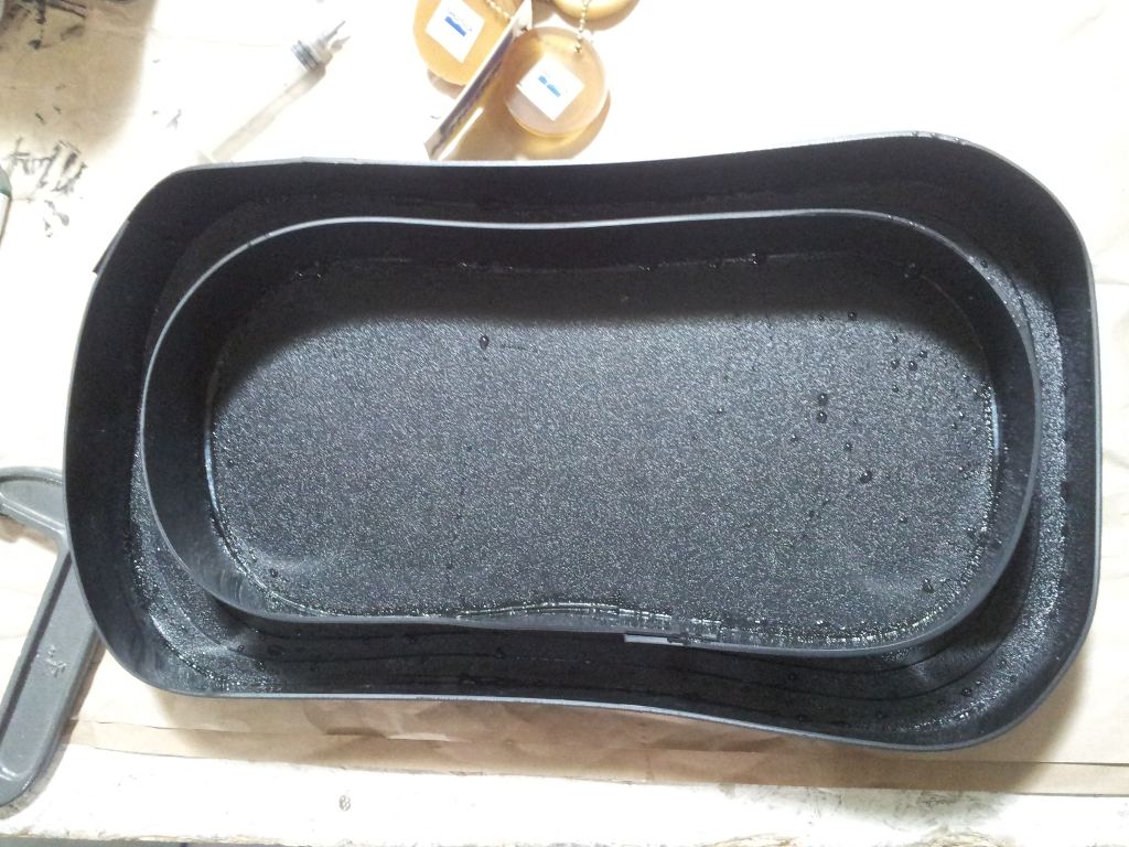
The empty mold. The water droplets are from the leak test; you don’t want your mold leaking on you when you pour it.
The next step was to mix up the mold material. It comes in two parts, and requires a mix ratio by volume, so I used a small scale to pour the exact amount required.

Pouring the exact quantities of each part.
Next is the first pour. The positive is suspended by toothpicks so that the silicone can fill in underneath the part. It must remain still until the mold cures.

The positive is suspended in the mold while it cures.

Toothpicks hold the scoreboard up slightly so that it’s not resting on the bottom.
Well, almost cures. We put a second pour on the outside so that there will be no visible lines on the outside from where the two halves of the mold split. The inner part needs to be at the halfway point, though, so this is a tricky mold. Fortunately, it works out.

After waiting for the bottom to get slightly harder, a second pour along the outside allows us to create a single mold half that has a parting line halfway up the inside and all the way up the outside. Very tricky.
After everything is set, we spray more mold release and pour the inner half. This part will separate from the rest of the mold.

The inside half is now curing. We have a two part mold.
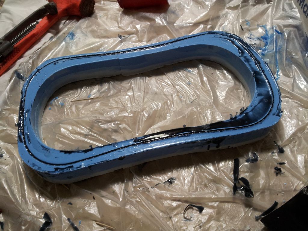
Once both halves of the mold are cured, the mold is separated and the original part comes out easily.

The original is being removed from the mold. The inner part separates easily from the rest.
And a new batch of silicone goes in. This time it is pigmented black. We experimented with a Shore 30A hardness material, but in a later cast we went up to 50A, and we may try 70A. These number indicate hardness of the material, or how floppy it is.
The cast is finished curing and about to be removed.
Taking it out once it cures is relatively easy. Just a little bit of pulling.
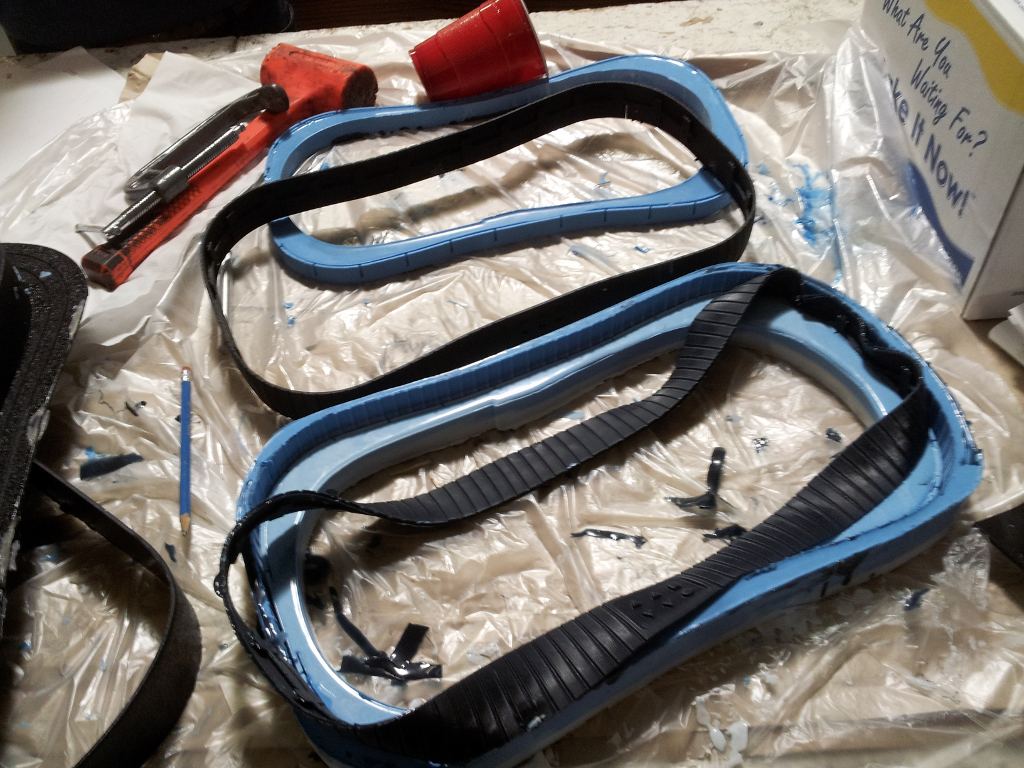
The cast comes out of the mold fairly easily. Sitting next to the original for comparison.
Every detail is perfectly preserved. The rubber material is much stretchier than the original ABS plastic.

The cast next to the original. It’s nearly perfect, and it’s the right feeling.

The buttons came out exactly right.
The part fits snugly between the front and back and everything screws together. A little paint on the buttons, and it’s ready to go!
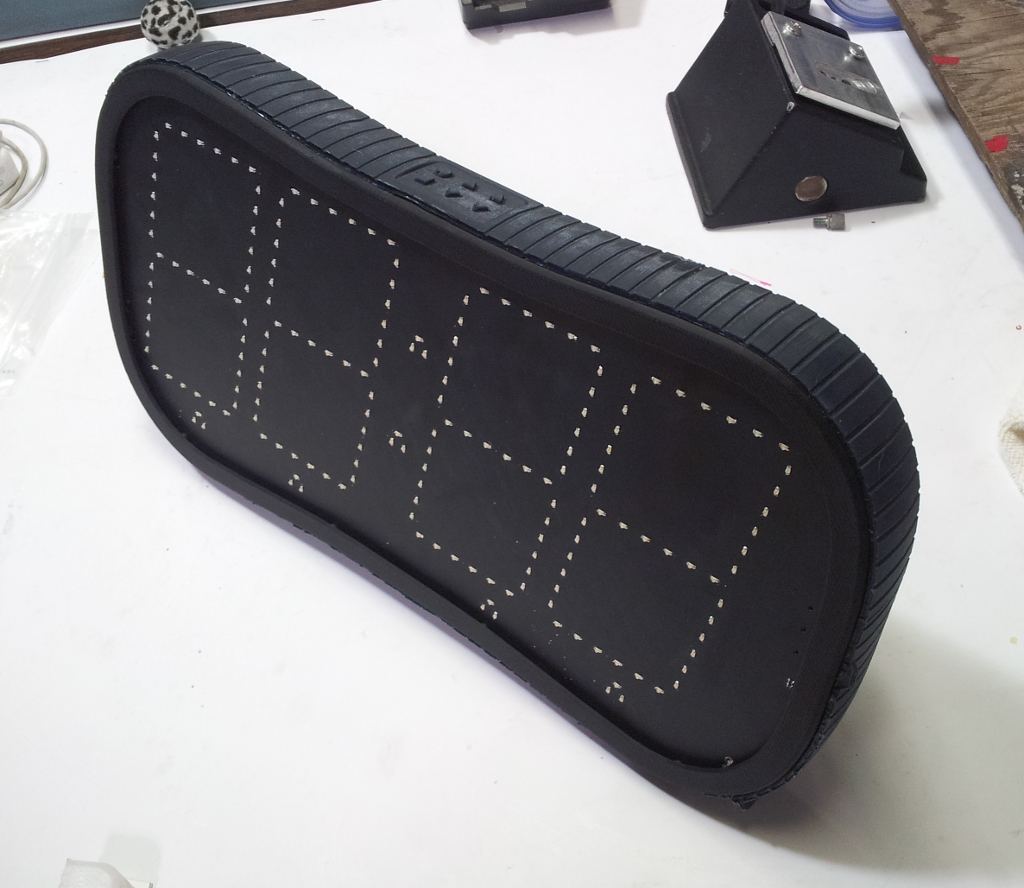
With the rubber around the scoreboard, it looks like a real product!
We’ve learned a lot through this experience. We have a good idea of exactly the process involved, how we can make some improvements for manufacturing, where on the part there may be issues, and how hard of a material we want to use. We also verified that the part fits correctly exactly as designed, and has the exact look we were striving for.
And we have a model that we can show investors and photograph.
Testing Everything
One of the reasons that product development takes so long is testing alternatives. You may see a product on shelves, but you won’t see the hundreds or thousands of alternatives that have been tried and tweaked before arriving at that final product. Our lab is littered with remnants of tests of various components, and our code history has numerous flags for different components.
The longest running example is the history of our remote control. We have, over the course of a couple years, tried a long list of options for the remote control. You can read some of that history of our remote here. That details the history only up until September. A lot changed in the 6 months since then. We’ve completely abandoned the regular RF remotes because they were unreliable and FCC approval would have been a pain. We switched to Bluetooth Low Energy (BLE or BT4.0), and have designed a completely new remote control around it.

Even during the switch to BLE, we evaluated 5 different companies to see which solution would work for us; BlueGiga, BlueRadios, LS Research, ISSC, and Linvor. Ultimately, BlueGiga has worked out the best and offered the most competitive price, but not without a lot of work.

Clockwise from top left: BlueGiga, ISSC, BlueRadios, Linvor, and LS Research
Over the course of the development time, we’ve also had to develop the firmware and hardware to make these solutions work. We have archived code for reading IR signals from the earliest remote controls. We have archived code for interacting with the RF remotes. And we have code for interacting with each of the Bluetooth modules. But nobody will see or use any of that. They will just be interacting with the final version; the best we could come up with after evaluating a LONG list of options.
But there are lots of other aspects we’ve been trying as well. We’ve been testing out different manufacturers of LEDs to get the brightest and most efficient LEDs we can. To do this we built small test circuits that have one segment of LED. Then we hooked them up and measured their brightness and viewing angles.
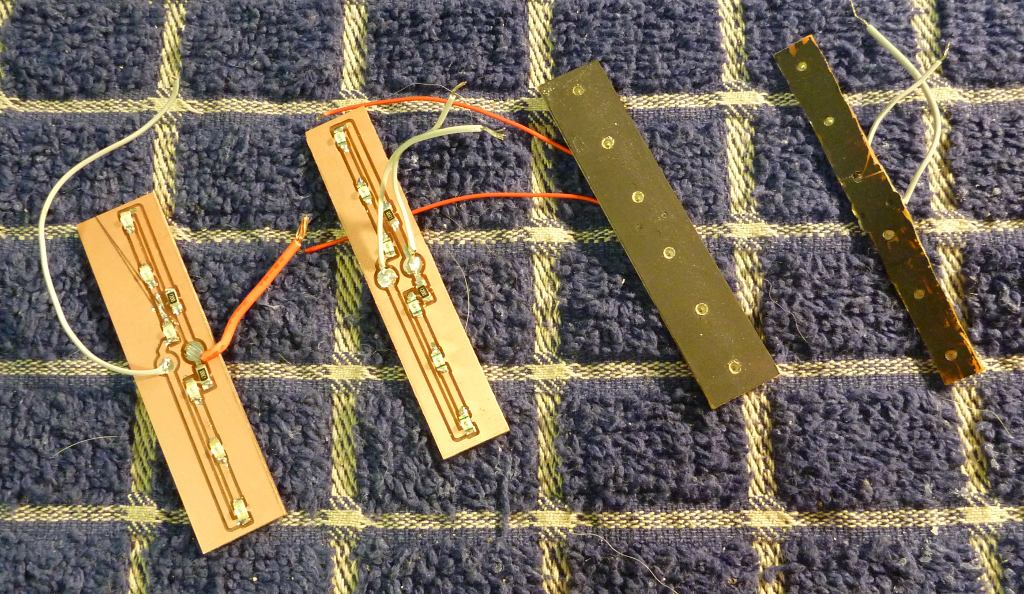
Testing two LED brands to determine which is brightest and has the widest viewing angle.
Another experiment involved tinting the screen to add contrast. In theory, sunlight reflecting off the scoreboard would wash out the LEDs and they would be hard to read. If a red filter were over it, then the sunlight would be mostly blocked, and only red light would escape and the scoreboard would be more visible in daylight. We went to a craft store and picked up some red films and ran the tests, but we also contacted professional plastics companies to see if our theory would hold and what kind of a cost increase we could expect.

Red film on the left, and no film on the right.
Our results so far are not definitive, but they’re leaning away from the red film. The increased cost is significant, but increased visibility is not. If anything, the red film reduces contrast because there’s now diffusion happening and the red in the sunlight isn’t contrasting with the red from the LEDs more than the black from no film is.
But our testing doesn’t include just the hardware and firmware. We’ve also been testing various options in manufacturing, logistics, and cash flow, and even our target market. We have no assumptions because every question we have is documented and verified with a corresponding test. Sure it takes a long time to perform all these tests, but we’re a small company. We can’t afford to get it wrong, but we can afford to perform quick little tests to make sure we’re doing it right.
As we go into production, there will continue to be things that we test, products that we build that never see the light of day but contribute to making the product better. And very few people will know all the things we’ve tried along the way. As long as they enjoy their product, though, and it does the job they want it to, then we’re ok with that.
Edge-lit company nameplates
As a weekend side project, and because I felt like improving company morale, and because my local hackerspace Sector67 has a laser cutter, and because I’ve recently been making LED strips to test different LEDs from alternative suppliers (that’s a lot of reasons), I got the idea to use my knowledge and spare parts to build some custom nameplates for everyone at Portable Scores.
The process was fairly simple (mostly because I had access to the right tools), and it turns out I had everything I needed already at Sector67.
First I experimented with laser engraving the nameplates. I realized that I needed to mirror the image so the engraving would happen on the back side and the front would be smooth.

Next I used the laser cutter to cut out some simple squares/rectangles of ABS for the enclosure. ABS leaves a gooey residue on the bed, so we had to create a bed on top of the bed. I did this by putting a sacrificial sheet of paper on the bed, then stacking a couple old pieces of material that had been cut out already and had large holes, then putting my ABS on top and cutting where the holes were. As the laser went through the ABS, the smoke and goo went onto the paper. It also burned the paper, but the paper took most of the goo. Some fires were started, but they burned out quickly.
I also used the CNC engraving machine to etch some circuit boards. This tool is much easier to use than the chemical etching method of making circuit boards. Here are all the parts ready to be assembled.
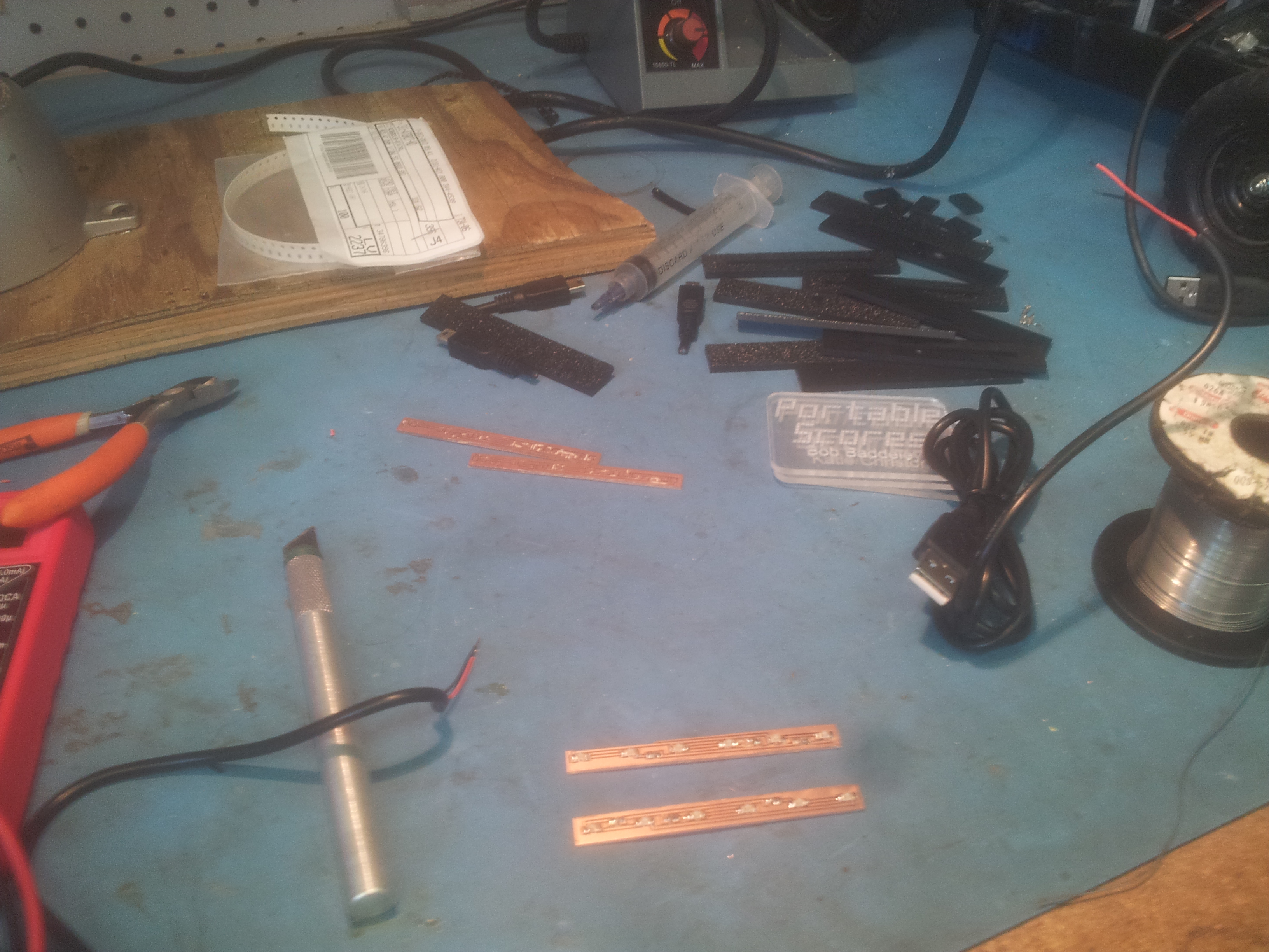
I then assembled the circuits, which use the same LEDs and resistors as the scoreboard, so I had plenty of parts.
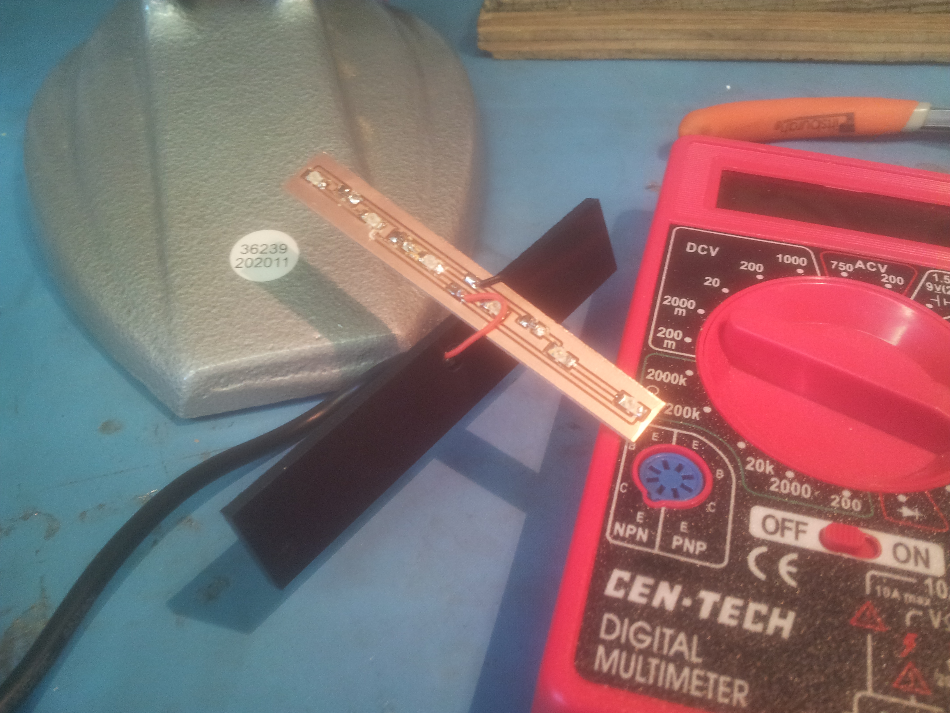 After that I used acetone to put all the plastic pieces together. The syringe is a great way of applying acetone and doesn’t stink while it’s in the syringe.

The nearly completed box is then hot glued to keep the circuit board stable and in position. In the next version I’ll size the circuit board to be an exact fit.
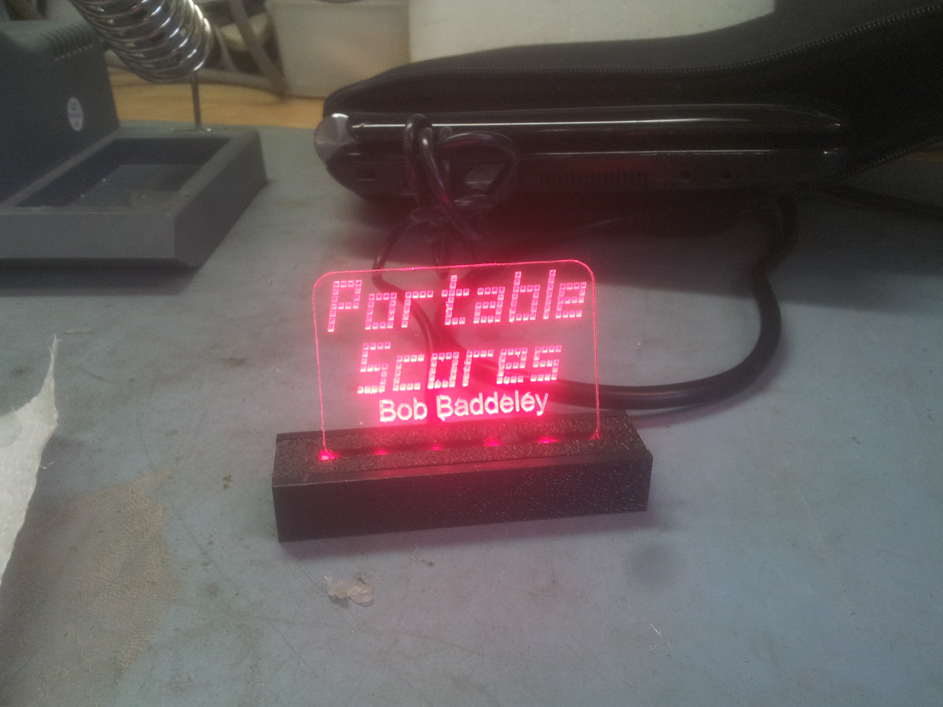
 Finally, the finished product. The display rests nicely on the LEDs and can easily be replaced.
Prototyping Circuit Boards
We’ve recently switched from IR remote controls to RF remote controls, giving us better range, better performance outdoors, and no longer requiring pointing the remote. In order to do this without printing all new and expensive circuit boards, we prototyped just the receiver part of the circuit and then attached it to the already assembled boards. This way we could test the circuit quickly. We used the CNC mill at Sector67 to do it. Here’s video of the milling in action.
And the partially completed circuits afterwards.

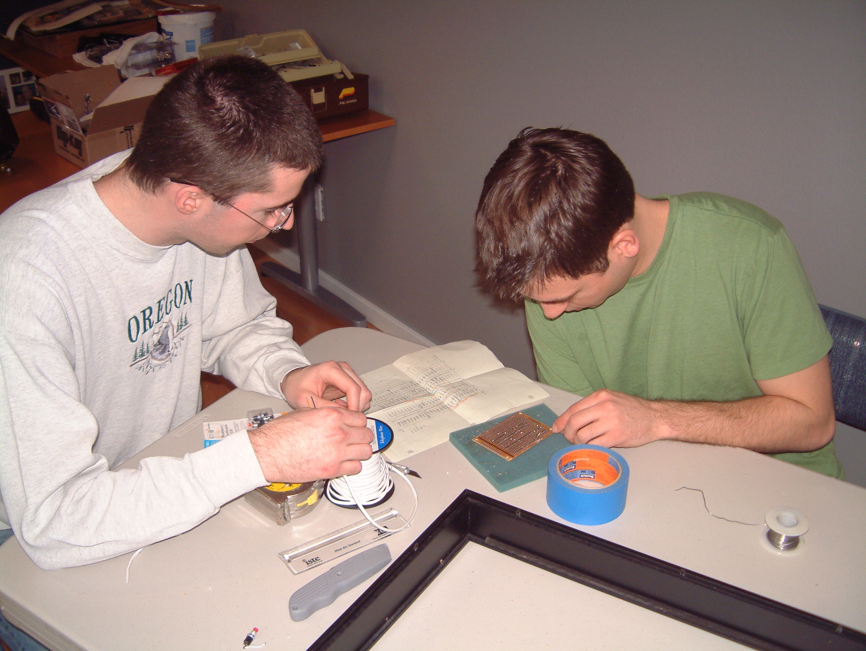
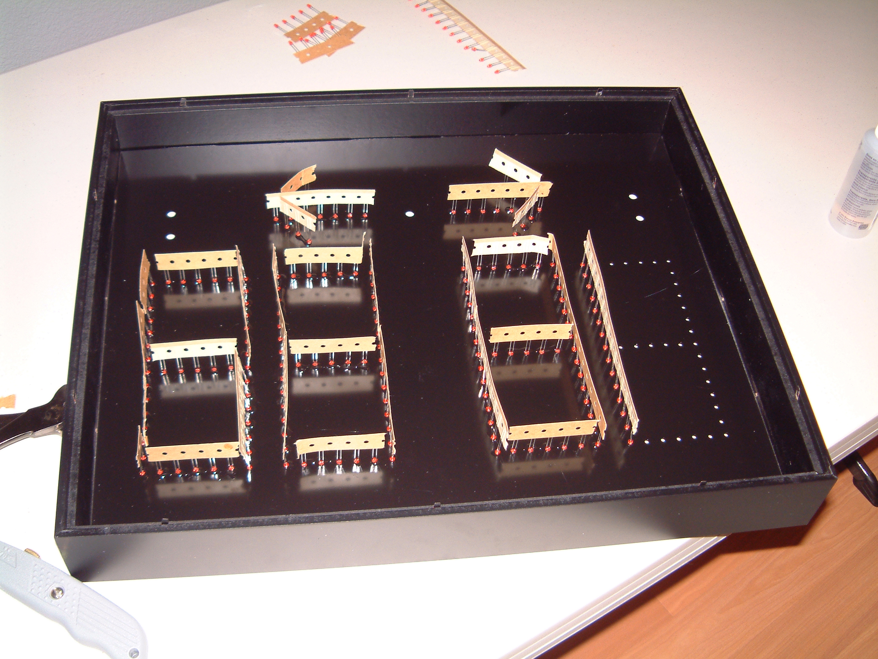
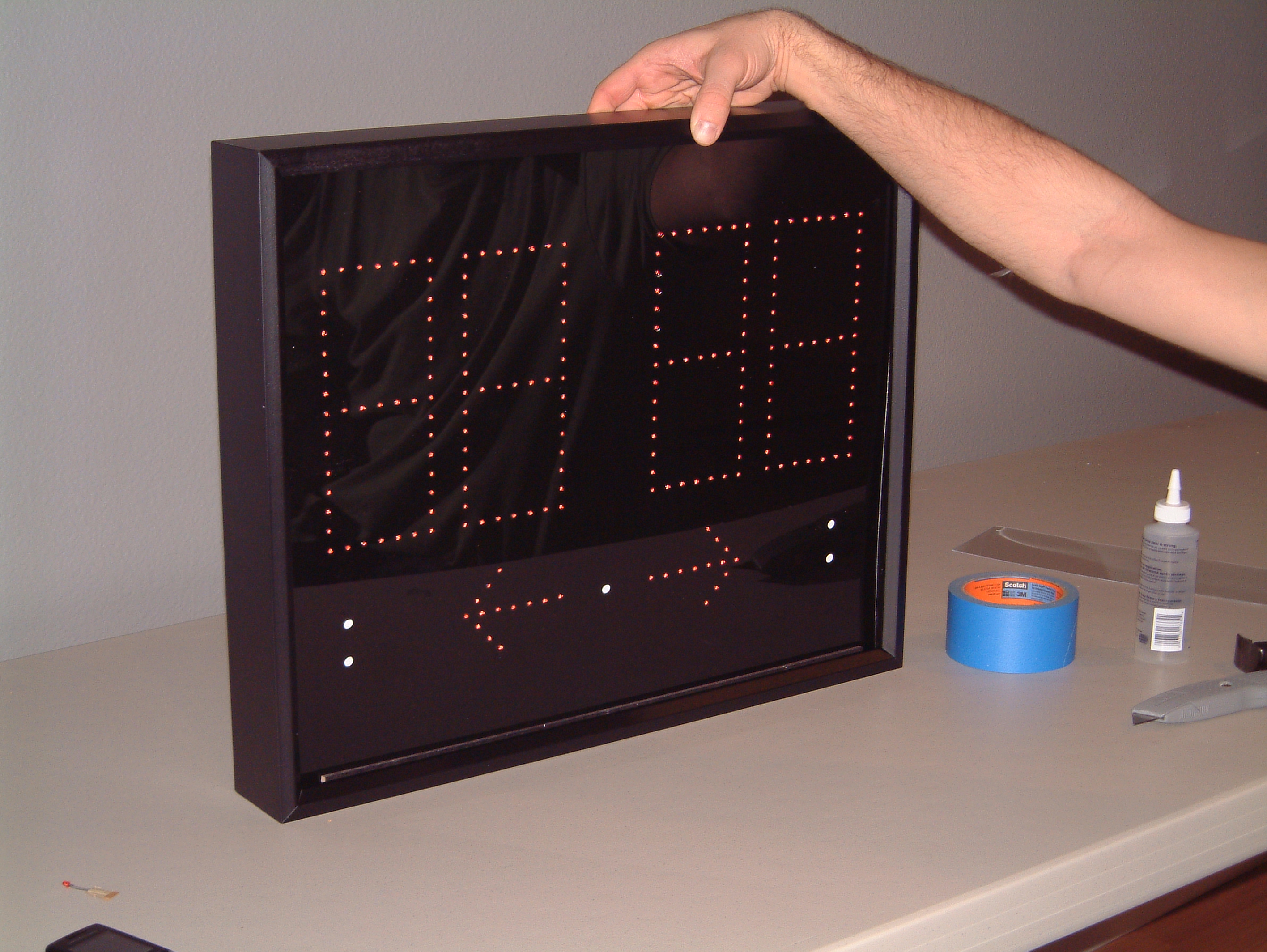
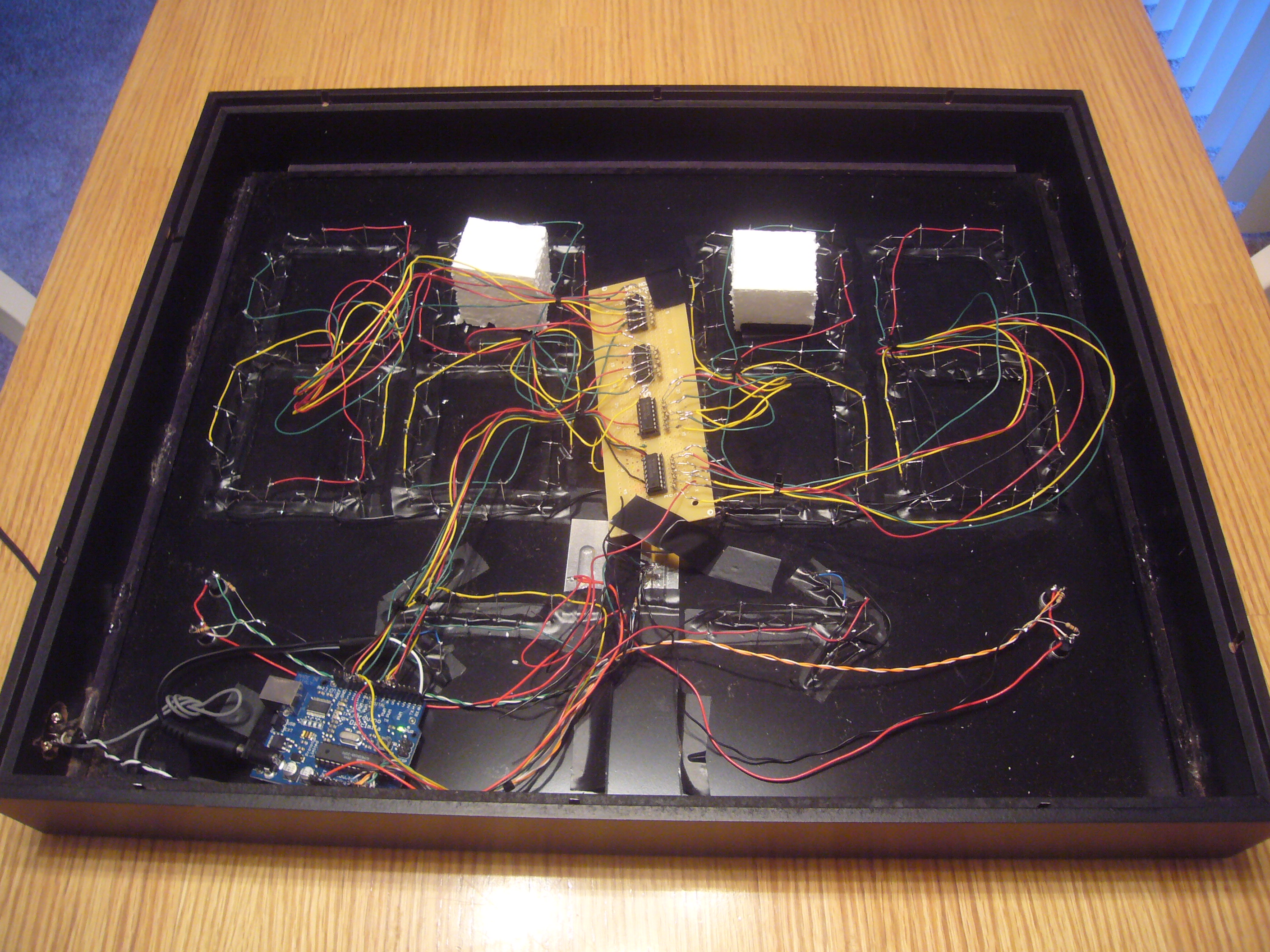
The first scoreboard
While digging around in my old photos, I came across photos of the first prototype of the scoreboard from 2006. It used a 16×20 frame, and we experimented with different finishes for the front.
-

- Drilling holes in acrylic for the LEDs

-

- We spray painted the back white. This turned out to be a mistake.

-

- Building our circuit from the sketched design.
-

- Putting the LEDs in and gluing them down.
-

- From the front.
-

- Wiring in the switches.

-

- Attaching the LEDs, putting in all the circuitry.

-

- Almost everything is together now.
-

- With a battery, buzzer, and now the remote control receiver, pulled from a wireless doorbell.

-

- It works! The scoreboard and two remotes.
24 hour app
Recently Portable Scores participated in Build Madison, a weekend hackathon to build cool things. We brought a scoreboard and offered it to a team that could build a cool project that incorporates it. The DigiTally has Bluetooth and USB and accessory switch ports, so integrating anything with it is pretty easy. Shannon had an idea for her gym to use the scoreboard to do interval training. In less than 24 hours, we built a pretty smartphone app that lets her control the intervals, then start and stop it and see the timing on the screen. Now she and her clients can all see the screen and concentrate on their workout instead of how much time is left.
Read a summary of the full event: http://www.capitalentrepreneurs.com/build-madison-recap-3/

Remote Progress
One of the biggest complaints with the scoreboard has been with the remote control. In fact, we’ve hated it ever since we started, but we had a few reasons for sticking with it. Lately, though, we’ve been working hard to get rid of those reasons and move away from the old remote and towards one that will give us a LOT more capability. We’ve been trying out different remotes to see what works, what doesn’t, and how to make them awesome. Here are a few so far.

From left to right, the prototype remote that we currently use, an RF remote, a smaller RF remote that works the same but has an additional button to prevent accidental presses, and a keychain IR remote. For reference, the big one is 5 1/2″ long, and the little one is 2 1/4″.
In short, the scoreboard is about to get a lot more awesome.
For the tech inclined, here’s what’s happening:
The prototype of the scoreboard uses an IR remote, essentially a universal remote. This is for a lot of reasons:
- Implementation was relatively easy. It only involved a single electronics component to receive the IR, and a single pin on the microcontroller. Some fancy code and I was on my way.
- The remote already existed. I could order it online and have it and I didn’t need to design a separate circuit board or a small enclosure or any of that.
- I didn’t need to worry about FCC approval for it. The remote was already FCC approved, and because it was using IR light, it didn’t need to pass emissions tests. It was just easy.
But there were some problems with IR:
- It’s directional, so you have to point it at the scoreboard.
- It’s not addressable, so if there were two scoreboards in a room, it could control both.
- It’s not fantastic in sunlight. If direct sunlight is blasting the remote, there is no way the remote control can compete and get a signal received correctly.
- It has limited range. It works great inside a room or court, but too far out and it gets really unreliable.
- It’s not scalable. Having to source these extra remotes is not good for the bottom line.
We’ve been wanting to solve these problems and more. With the RF remotes, we get a lot of benefits:
- Omni-directional (it works even if it’s still in your pockets).
- Much better range (so it really does work across a field).
- Addressability (so there’s no conflicts with other scoreboards, but it also means you could intentionally control two scoreboards with one remote).
- Size/design (doing it myself with RF means I can make the design however I want).
- Sunlight doesn’t matter.
There are some drawbacks:
- RF components are more expensive overall than the IR components, but we’re adding features.
- We now need FCC approval for the remote, which is acting as an intentional emitter, and subject to 47 CFR 15.231 (I know this without looking). It will need to pass inspection by a third party tester, and it will not be cheap.
- It’s a long road ahead to get the remote and receiver designed and tested and ultimately FCC approved.
In the long run, this is the right way to go for the scoreboard. It will remove a lot of the pain points that exist with the scoreboard, and it adds functionality that people have been asking for. Plus it adds a little bit of flair to the accessory switches, but that’s a little down the road.