Pretty pretty lights
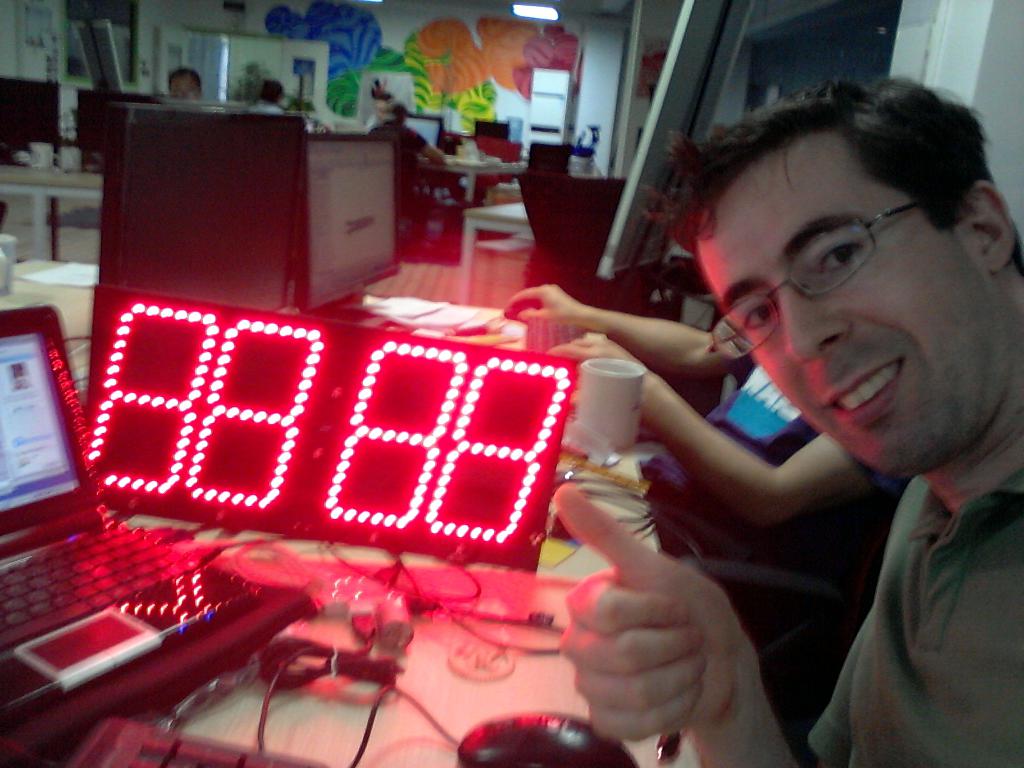
In playing around with the scoreboard’s ability to be controlled by a computer or smartphone, I wrote a quick script that does a few different effects on the board. It’s strangely mesmerizing.
Rendering of the final product
We’ve been working on the design of the scoreboard a lot, and we’re finally happy with what we have. Here’s a video of the rendering we really like. There are a lot of features to point out.
- Clear polycarbonate face is the same material used in bulletproof glass.
- Kickstand for standing upright on the ground or table.
- Tripod mount for putting it up high.
- Holes for mounting on a wall.
- Convenient hand holds for carrying.
- Buttons on top for controlling it, with the buttons molded into the rubber grip for tight protection against water.
- A rubber grip around the edge to add water resistance, and protect it from drops and scrapes.
Now we just need support to help us make it to production!
Building a batch of enclosures
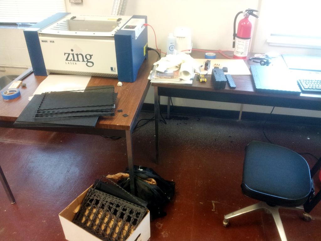
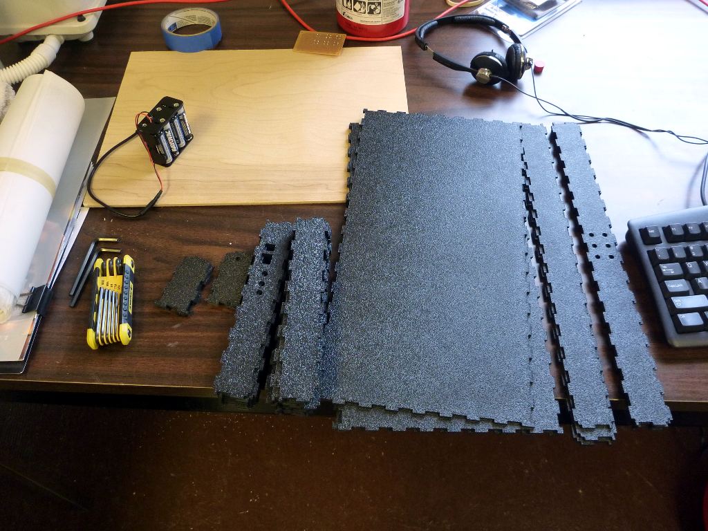
Today I spent most of the day laser cutting sheets of ABS plastic for some basic enclosures. It took about 3 hours last night and this morning to prepare the 4×8 sheets of 1/8″ thick plastic into pieces that were the right size for the laser cutter. I had to measure out long lines, then score them repeatedly with a razor blade, then bend the sheets until they snapped with a blast like a gun shot.
Then today it took 4 hours to cut the plastic on the cutter. I was fortunate to know someone who has access to one and could share it, and for a few hours I cut sheet after sheet of material. Afterwards, the ABS left a strange goop on the cutting surface, so I spent a couple hours cleaning it in acetone.
The pieces look great, fit perfectly, and smell awful. The box of parts will clear a room in no time, and I’ve been asked to find somewhere else to store them other than Sector67. Home isn’t a good option either, so they’re currently in the trunk of the car. I’m not looking forward to opening it.
Table Tennis Accessory Switch
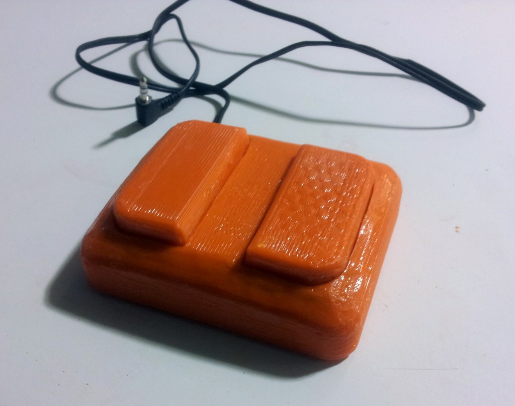
I printed the first prototype accessory switch and assembled it recently. This one is for table tennis. The idea is to mount one under each side of the ping pong table, plug them into the accessory ports on the scoreboard, and be able to whack the buttons when you score to keep track of the game without losing focus or interrupting play.
The design is very simple, the prototype works well, and I have a model that I can now take to factories and show off to people. Production of this unit should be a LOT easier than the scoreboard itself, and it can easily be replicated and modified by anyone else who wants to make custom accessory switches for their scoreboard.
For details about the construction and design, see the wiki page on the buttons.
PCB Assembly Party
Last night was the PCB assembly party, in which 20 units went from bare boards and components to assembled boards. Some crucial components were missing from the BOM so we weren’t able to call them complete, but that was my fault. In fact, I had them, but on a test unit I had pre-assembled they kept failing, so I didn’t want to risk continuing to use the faulty components and instead sourced a different component from Mouser). But the vast majority of the pieces were placed last night. It took about 10 people, who contributed for varying amounts of time. Some stayed as long as 10 hours.
We learned a lot and developed some new methods, and people became very comfortable with SMT assembly. The first part of our setup included placement of the LEDs. Because these need to be a cleaner finish with the solder because they are externally visible, we used solder paste and baked the boards on a hot plate. This was an interesting stage because the heating of the board was such that the board warped almost immediately as the bottom of the board got hot and expanded but the top didn’t expand to compensate. We adjusted our methods to compensate, only doing half the board at a time, and holding it flat as it baked. This process worked well, and soon all the fronts were done. By soon, I mean it took approximately 4 hours to do all the fronts.
The backs were all hand soldered, and the microcontrollers were the most challenging, requiring a microscope and very careful hand for hours. This will hopefully be the only batch; in the future the boards will be done in bulk on automated machines.
The party was fueled by pizza and beer, which in retrospect were poor choices because of the effects of pizza fingers and manual dexterity, but it was a good time, and many hours were saved by many cool people, some of whom went from never having done surface mount work to being experts in a matter of hours.
Click on the images to open them full size.
Temp enclosure ready to go
A couple weeks ago I gave a presentation in which a venture capitalist, after hearing the presentation, asked to buy a unit. I still don’t have tooling done for the enclosure, so I had to design a new enclosure that could be laser printed. The temp enclosure fits around the test board perfectly, and is held together with super glue, which is a really good adhesive for acrylic. This temporary enclosure is slick, easy to cut and assemble, and works well. I’m less happy with the buttons, but I couldn’t find any better ones at the electronics market that would fit. This unit is now ready to go and I can continue working on the design of the real enclosure.
The construction of this unit was only a minor distraction, though, as it forced me to get a lot of work done on the firmware, get some more components of the hardware working better, and this temporary enclosure is a good backup design in case I need to produce units quickly between now and when I have the prettier version tooled and ready to go.
Populating the earth – one board at a time
Last week my boards arrived. I immediately set about populating one to test. With ~200 LEDs, ~35 MOSFETs, ~70 resistors, and ~30 other components, that’s a lot of soldering of tiny surface mount parts. The first board worked great, and I only discovered one flaw with the board (so far), which I was able to fix with some creative cutting and wiring.
The next board I managed to destroy in a fit of fatigue that had me making poor decisions and soldering poorly.
The new second board was populated today and will be sent to my beta tester in Michigan, an older guy in a volleyball league who claims that nobody playing can remember the score two minutes into the game and that they really need a scoreboard.
Full size boards arrived!
The first revision using the full size PCB has arrived! This is a rough draft; an attempt to see what happens trying to produce the board at the full size. There will be at least one more revision to make changes to components or tweak the locations of components to move them closer to edges or adjust to the shape of the enclosure and insert mounting mechanisms.
Next up is hand populating it to test the board and make sure all the components and the schematic work, and most importantly to make sure that the board at its current size will work outside and be visible.
This is an exciting step, and I’m really excited to see what happens with it.
First revision of the board sent out
As of today, the first revision of the board (actually the third revision, but the first one at full scale) has been sent to the PCB fab house, and we should get the boards within a week. This is still a prototyping board, and an opportunity to make sure the components all work and that the board is legible in daylight from a distance. We got about as far as we could get with my small scale prototype boards, which contained all the components and circuitry on a small 4×5″ board. Now we’re moving up to what we hope is normal sized.
For those unfamiliar with the terms, the PCB is a printed circuit board. It’s the sheet of fiberglass with copper traces etched on it that holds all the electronic components and the LEDs. It will set inside the enclosure.
A lot of people have asked why not have multiple PCBs with the different sections. With this approach, a single PCB is manufactured, which already has the black color so no additional steps are necessary, and which can be assembled quickly, and which doesn’t require expensive cable assemblies attaching all the parts together or another piece of plastic to hold it all into a single frame. It’s still small enough to be manufacturable and cost effective, and it’ll still fit through the pick and place machines and solder ovens, so it should be easy to automate production, and it should look good.
We’ll see how everything works when we get the boards back and I can spend a day hand soldering all the components on a prototype board.
Talking to Android phones
A couple days ago Google announced support for accessories attached to Android devices. These accessories are based on the Arduino platform. What does this mean for the scoreboard? It means that certain Android phones and tables can now be hooked up to the scoreboard to control it. We’re already working on an app for that so that you can plug the usb cable into your Android device and the scoreboard and use our Android app to adjust the score or time or whatever. We’re really excited about the potential with this new development, and we’re hard at work to make it happen.
Update June 9:
The app is really close. The UI works, but the USB accessory support is so new that the emulators can’t use it, and we don’t have any devices that are new enough to support it either. For now it runs alone, but as soon as we can, we’ll update it to work with the scoreboard.


